- Home
- Applications
- CCTV and PoE cameras
Application
CCTV and PoE camera links over fiber
A camera run is a power problem before it is a data problem. Copper Ethernet stops at 100 m, the PoE budget has to be booked against the cabinet you actually have, and the pole outside usually has neither mains nor a technician on call.
7 catalogue models · 3 families
01
What the link has to solve
A surveillance install tends to fail at the same two places: the 100 m limit of the camera port, and the power at the far end. Fiber answers the first — one strand carries the stream back to the cabinet — but it does not carry electricity. Power is still decided locally, either by a PoE switch inside the cabinet or by a single-port injector beside the camera.
Three shapes cover most sites. Inside a building, an 8- or 16-port PoE switch with one or two fiber uplinks feeds the camera floor and hands the traffic back over single-mode. On a perimeter pole, a PoE converter or an IP67 injector takes the fiber and delivers one PoE port to the camera. Where a camera sits more than 100 m of copper from anything, a PoE extender repeats the port without adding a second switch.
02
Sizing: ports, distance, power, temperature
Ports first — count cameras, not runs. A four-port PoE switch with a fiber uplink (LNK-IMC104GP) covers a mast with three or four cameras; an eight-port model (LNK-IMC208GP) covers a gate cluster and still leaves two fiber ports for a ring or a second building. A single-camera leg is usually cheaper as a converter: LNK-IMC3012P60-SFP gives one PoE port plus one SFP slot whose reach is set by the module you fit.
Distance second. The catalogue prints a figure per model: 550M or 20KM on the gigabit fixed-optics units, 2KM or 20KM on the 100M ones, and "depends on the SFP module" on every SFP variant — there the number comes from the optic, not from the converter. A 20 km LX module on a 2 km run is money spent on nothing; a 550 m multi-mode part on single-mode simply will not light.
Power third, and this is where budgets are lost. The catalogue lists 802.3at models at 30 W and 60 W, and LNK-IMC205GHP-SFP is printed as 802.3bt 90 W. A dome with IR and a heater can sit at the top of that range. The switches themselves take 48~57 VDC, so the supply belongs in the bill of materials: the catalogue pairs LNK-IMC104GP with NDR-120-48 (120 W), LNK-IMC208GP with NDR-480-48 (480 W), and LNK-IMC205GHP-SFP with NDR-480-48.
Temperature fourth. Where a range is printed it reads 0~70 °C on the industrial converter families, and several PoE switch entries carry no temperature line at all. If the cabinet sits in direct sun, put the question in the enquiry — a range the catalogue does not print is confirmed with the quotation, not guessed here.
03
Where installs go wrong
Almost every field fault we are asked about traces back to one of the cases below. They cost more than the hardware difference between a 30 W and a 90 W part.
- 01 A 30 W PSE on a camera that draws 34 W at night. The port negotiates, then the camera drops at 02:00 — check the camera peak, not its average.
- 02 One end single-mode, the other multi-mode. Reach, wavelength and fibre count have to match; a duplex LC pair and a single-fibre BiDi pair are not interchangeable.
- 03 The injector at the pole has no supply. An injector needs its own input (12~48 VDC on the LNK-INJ301 series); PoE does not travel down the fibre.
- 04 An extender chain used as a switch. LNK-PoE-E1 and LNK-PoE-E4 are printed at 120 m of additional reach, not as a second uplink.
Recommended models
What we would quote for this link
| Model | Ports | Input power | Transmission distance | Page |
|---|---|---|---|---|
| 4x PoE + 1x1000Base-FX (SFP, SC, FC, ST ) | 48~57VDC | 550M or 20KM | p18 | |
| 8 x PoE+2 x 1000Base-X (SFP,SC, FC, ST ) | 48~57VDC | 550M or 20KM | p19 | |
| 4x PoE + 1x 10/100/1000T + 2x 100/1000X SFP | 48~57VDC | depends on the SFP module | p19 | |
| 1xRJ45+1xSFP 1000Base-X or 100Base-FX ( auto-detect ) | 48~57VDC | depends on the SFP module | p12 | |
| 1 RJ45 RJ45 input + 1 RJ45 PoE output + 2x M22 waterproof RJ-45 | 90~264VAC | 100M | p29 | |
| 2 x RJ45 + 1 x DC | 5V/9V/12V/19V DC 25W 3.5A Max | 100M | p29 | |
| 1 RJ-45 PoE/PD input + 4 RJ-45 PoE/PSE output | 48V DC | 100M | p30 |
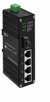
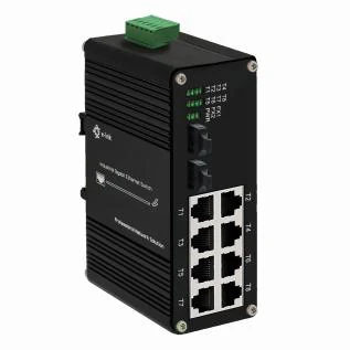
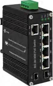
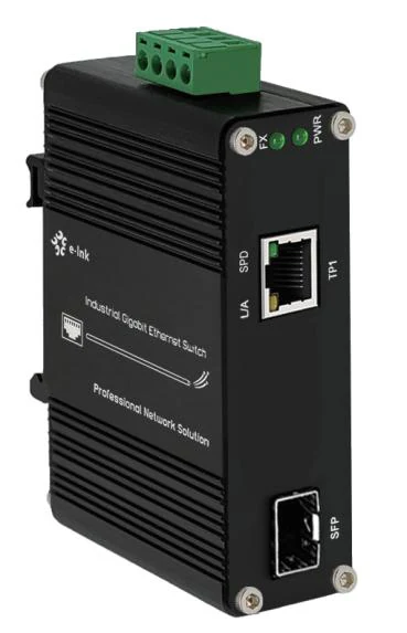
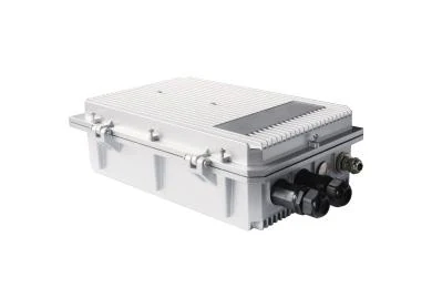
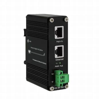
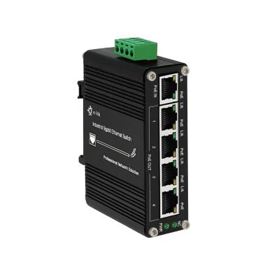
Specifications copied from the catalogue pages cited on each product page. The supply shown beside a switch is the one the catalogue recommends for it.
Price, minimum order quantity and lead time are not published for any model — they are confirmed with the quotation. Specifications are transcribed from our factory's catalogue; where a field is not printed there it is left out rather than guessed.
Send the drawing, get the model numbers back
Mark the cameras, cabinets, spans and the power available at each site. We answer with the models, the optics for each span, and the supply each cabinet needs — with the quotation.